You are here
In-situ TEM - martensitic transformations and twinning in Cu-Al-Ni
by Niva Zárubová
Original work published in Acta Materialia
Research team: N. Zárubová, V.Novák, J. Gemperlová, A. Gemperle, Z. Dlabáček, P. Šittner
Content
- Martensitic transformations and twinning processes in CuAlNi single crystals
- In-situ transmisson electron microscopy experiment
- Stress-induced transformation of β1 <-> β1’ - video
- Stress-induced transformation of β1 <-> β1’ - nucleation
- Selected frames from video illustrating the stress-induced β1 <-> β1’ transformation
- Stress-induced reorientation between two γ1’ variants - video
- Stress-induced reorientation between two γ1’ variants - description
- Stress-induced transformation β1 -> γ1’
- Stress-induced transformation β1 -> γ1’ – habit plane
- Literature
Martensitic transformations and twinning processes in CuAlNi single crystals
Depending on the temperature, applied stress and sense of load, the cubic austenite phase in CuAlNi single crystals transforms in two different martensitic phases.
- cubic to orthorhombic β1 (D03) <-> γ1’ (2H) ,
- cubic to monoclinic β1 <-> β1’ (18R) ,
Furthermore,
- the orthorhombic martensite phase may transform under application of larger stress to monoclinic phase γ1’ <-> β1’ ,
- the monoclinic phase may transform under application of larger stress to trigonal phase β1’ <-> α1’ (6R)
- the orthorhombic γ1’ phase may deform by twinning.
All the processes proceed via propagation of mobile interfaces. Selected examples from in-situ TEM experiments are given below.
In-situ transmission electron microscopy experiment
In order to investigate the mechanism of the transformation and twinning processes on the microlevel, we have carried out series of in-situ mechanical experiments inside the transmission electron microscope where the crystal defects can be observed in motion.
Tensile samples of 1.7 x 5.5 x 0.07 mm3 for the in-situ TEM straining were prepared by spark cutting and grinding. A mounting hole of 0.6 mm in diameter was drilled at each end of the sample (see the figure below). The central part of the specimen was thinned to electron transparency by the double jet electropolishing. The preferred areas of observation are indicated by green arrows.
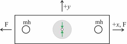
The samples were strained in tension at room temperature in a JEM 1200EX microscope equipped with a double tilt straining stage (x-tilt 30º, y-tilt 10º, max. load of 25 N) designed and constructed at the Institute of Physics ASCR.
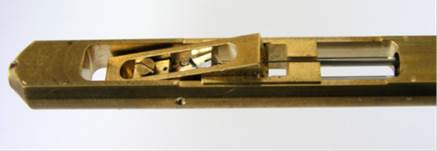
Tip of the specimen holder with the tilting cradle
For more details of the in-situ TEM straining experimen, including the stress distribution around the hole see the PPT presentation.
Transformation processes taking place during loading/unloading were video-recorded by an Olympus Mega View III camera. Only the applied load was recorded during the in-situ TEM experiment, the elongation of the thin foil sample was not evaluated. Some videos are shown further in this presentation. Detailed structural investigations were carried out under static stress in both the bright field (BF) and dark field (DF).
Stress-induced cubic to monoclinic β1 <-> β1’ martensitic transformation
In the process of the stress-induced cubic to monoclinic β1 <-> β1’ martensitic transformation, the β1’ phase appears as a family of plate shaped particles in the austenite matrix that grow with increasing load applied in the in-situ TEM experiment. When the applied load decreases, the β1’ martensite plates disappear.
Nucleation of the stress-induced cubic to monoclinic β1 <-> β1’ martensitic transformation
The β1’ martensite particles always nucleated at the already existing γ1’ martensite particle.
The β1’ needles were wedge shaped and propagated by a jerky movement of the needle. During unloading, the needles shrank back into the austenite β1 matrix. The jerky movement of the β1’ martensite needles could be easily controlled by the external load.
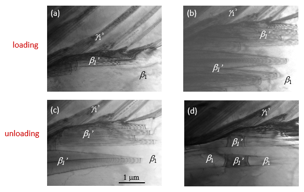
Details of the stress-induced β1 <-> β1’ martensitic transformation
(a) The β1’ martensite starts to nucleate at the β1/γ1’ boundary
(b) With increasing stress, the β1 → β1’ transformation takes place by propagation of the β1’ needles into the austenite matrix
(c) With decreasing stress, the reverse β1’→ β1 transformation takes place by shrinking of the β1’ needles back into the austenite matrix
(d) Eventually, the martensite β1’ needles completely disappear
Stress-induced reorientation between two variants of the orthorhombic γ1’ martensite phase
Reorientation between two variants of the orthorhombic γ1’ martensite phase was observed when the stress was changing. The γ1’(V1) variant transformed into γ1’(V3) in response to increasing stress (detwinning). During unloading, the γ1’ (V1) needles returned to their original shapes (twinning). For definiton of the martensite variants, see the original work.
Load increases
Load decreases
Stress-induced reorientation between two variants of the orthorhombic γ1’ martensite phase - detailed description
Three selected stages of the stress induced reorientation of the γ1’ martensite variants during the loading / unloading are shown.
The typical bow-like contrast visible in the transforming γ1’ (V1) needles indicates that both the detwinning and twinning processes are controlled by movement of twinning dislocations, similarly as in the case of NiMnGa.
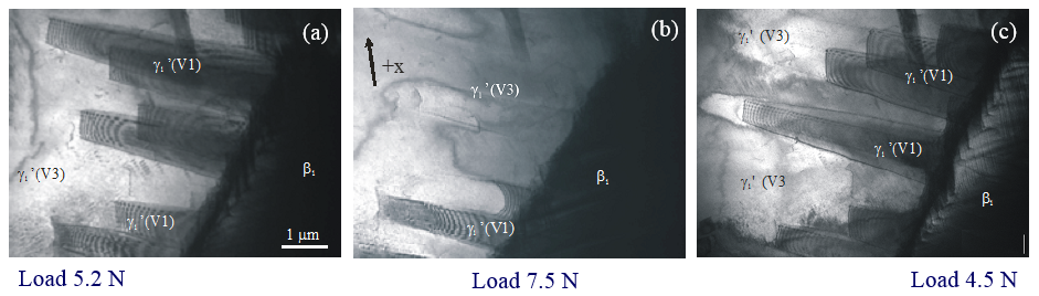
Reorientation of the γ1’ martensite variants.
(a) Twinned γ1’ martensite near the boundary with the austenite matrix. The γ1’ (V1) needles are well developed at lower stress levels.
(b) The same area as in (a). With increasing stress, the γ1’(V1) variant transforms into γ1’(V3). In the upper part of the figure, the γ1’(V1) needles have already disappeared.
(c) The same area as in (a), (b). With decreasing stress, the reverse transformation γ1’(V3) <-> γ1’(V1) takes place.
Stress-induced cubic to ortorhombic β1 -> γ1’ martensitic transformation
Though the internally twinned needles of the γ1’ martensite were frequently observed in the in-situ TEM experiment, their growth from the austenite matrix was never observed.
The burst-like nucleation and growth of the γ1’ martensite upon loading made it impossible to record any details of the β1 <-> γ1’ transformation.
The β1/γ1’ habit plane interfaces having the zigzag character were stable and did not move under further loading or unloading.
The reverse γ1’ <-> β1 transformation was never detected upon unloading.
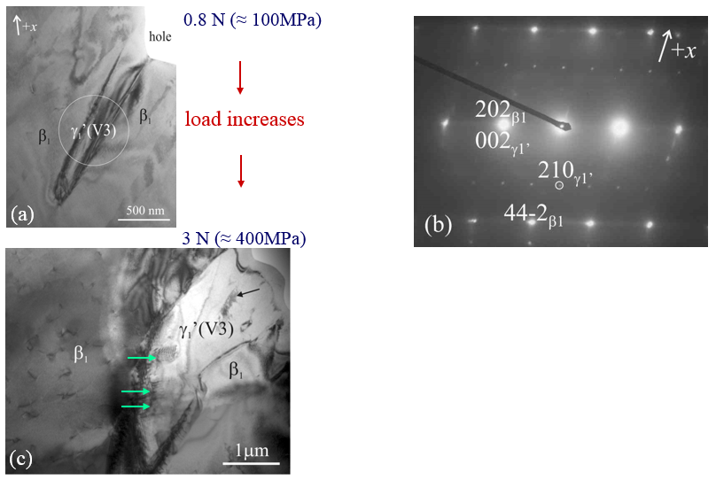
Nucleation and growth of γ1’ martensite.
(a) The first γ1’(V3) martensite needle appearing at the hole’s edge. The arrow indicates the longitudial axis of the sample.
(b) Diffraction pattern from the encircled area in (a). It represents a superposition of β1 austenite and γ1’ martensite.
(c) The same area as in (a) under a higher applied stress; the γ1’(V3) needle suddenly grew up (its original size and position is still visible indidated by the black arrow). The green arrows point to another γ1’ variant existing inside the γ1’ (V3) variant.
Habit plane between austenite and stress-induced γ1’ martensite
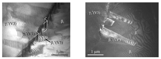
The figure bellow shows in detail the habit plane - boundary between the β1 austenite and γ1’ martensite.
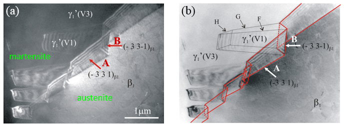
Zigzag boundary between the β1 austenite and the twinned γ1’ martensite (V3 and V1 variants).
The boundary is formed by two segments, A, B, which were identified as {331} type austenite β1 planes.
A – β1/ γ1’(V3) interface, B – β1/γ1’(V1) interface,
F, G, H – interfaces between γ1’(V1) and γ1’(V3) martensite variants.
The martensite is twinned only near the boundary. The wedge-shaped needles, identified as the γ1’(V1) martensite variant, are surrounded by the large γ1’(V3) martensite variant that forms the rest of the martensite plate. The zigzag habit plane between austenite and γ1’ martensite thus consists of two types of differently oriented facets.
Literature
[1] Dlabáček Z, Gemperle A, Gemperlová J. Proc. 13th European Microscopy Congress 2004;1:417
[2] Coujou A, Lours Ph, Roy NA, Caillard D, Clement N. Acta Metal 1990;38:825
[3] Zárubová N, Gemperle A, Gemperlová J. Mater Sci Eng A 2007;462:407
[4] Novák V, Šittner P, Zárubová N. Mater Sci Eng A 1997;234-236:414
[5] Novák V, Šittner P. Mater. Sci. Eng. A 2004;378:490
[6] Bekker A, Brinson LC. Acta Mater. 1998;46:3649
[7] Zhang XY, Brinson LS, Sun QP. Smart Mater. Struct. 2000;9:571
[8] Zárubová N, Gemperlová J, Gemperle A, Dlabáček Z, Šittner P, Novák V. Acta Mater 2010;58:5109
[9] Zárubová N, Gemperlová J, Gemperle A, Dlabáček Z. Proc. ESOMAT2009, Prague 2009.
[10] Zárubová N, Gemperlová J, Gärtnerová V, Gemperle A. Mater. Sci. Eng. A 2008;481-482:457
[11] Rodriguez C, Brown LC. Metallurgical Trans. A 1976;7A:265
[12] Otsuka K, Wayman CM, Nakai K, Sakamoto H, Shimizu K. Acta Metall. 1976;24:207
[13] Novák V, Malimánek J, Zárubová N. Mater. Sci. Eng. A 1995;191:193
Quick Links
Copyright © 2015 OFM AV ČR, v. v. i.