You are here
In-situ TEM - deformation twinning in Ni-Mn-Ga
by Niva Zárubová
Original work published in Acta Materialia
Research team: N. Zárubová, Y. Ge, O. Heczko, J. Gemperlová, A. Gemperle, Z. Dlabáček, P. Šittner, S.-P. Hannula
Content
- Magnetic shape memory
- Structure of the martensite phase in NiMnGa alloy
- Twin hierarchy in the NiMnGa martensite
- In-situ transmission electron microscopy experiment
- Twin variant reorientation during straining the NM martensite in NiMnGa
- Movement of twinning dislocations during the twin variant reorientation
- Movement of twinning dislocations during the twin variant reorientation
- Reorientation process in detail
- Twinning dislocations in detail
- Twinning of NM martensite upon unloading
- Mechanism of twinning via motion of twinning dislocations
- Literature
Magnetic shape memory
NiMnGa is a ferromagnetic shape memory alloy (FSMA) with many potential engineering applications, particularly in the area of sensors and actuators. Since the martensite phase is strongly magnetically anisotropic, magnetic domains are tightly bounded with the crystal lattice of martensite variants and movement of twin interfaces in the martensite phase is easy, large material strains can be achieved in these alloys by applying magnetic fields or combined magneto-mechanical forces as the animation below shows.
Conventional ferromagnetic material Magnetic shape memory material
If the twin boundary is not mobile (left), the magnetization (arrows) rotate when the crystal is exposed to rotating magnetic field.
If the twin boundary is highly mobile as in NiMnGa martensite (right), the twin boundary moves instead of the rotation of the magnetization.
Structure of the martensite phase in NiMnGa alloy
The in-situ TEM experiments were performed on a Ni52.4Mn27.3Ga20.3 (at.%) alloy. The cubic austenite phase of this composition transforms martensitically and magnetically (transformation temperatures Ms = 398 K, Af = 408 K, Tc = 380.2 K) to nonmodulated /NM/ tetragonal martensite (cell parameters a = 0.549 nm, c = 0.661 nm).
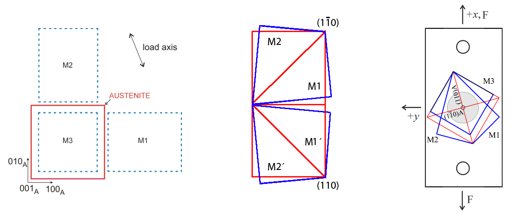
Three martensite variants M1, M2 ,M3 can form from the cubic austenite phase as shown in the left figure below. Each two of the three martensite variants can form a compound twin with the twin plane derived from a {101}A plane in the austenite phase (middle figure).
The crystallographic orientations of the three martensite variants M1,M2,M3 with respect to the external coordinate system are marked in the right figure showing orientation of the parent austenite and the martensite variants M1, M2, M3 in the TEM foil - see also the PPT presentation.
Twin hierarchy in the NiMnGa martensite
Microstructure of the thermally induced NM martensite consists of large domains separated by incoherent boundaries. The lamellar structure of the domains is formed by internal compound twins with (101)M or (011)M twin planes.
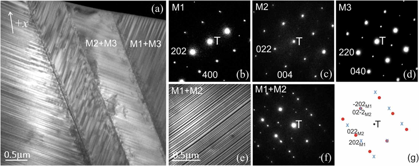
Structure of the thermal tetragonal martensite. (a) An area with the twinned domains M1+M3 and M2+M3. The arrow indicates the longitudinal axis of the foil. (b), (c), (d) Selected-area diffraction (SAD) patterns from variants M1, M2, M3, respectively. T is the transmitted beam. (e) A twinned domain M1+M2. The twin plates are in the edge-on position (perpendicular to the image plane). (f) A superposition of SAD patterns of variants M1 and M2 in (e). (g) A key-diagram to (f); variant M1 – crosses, variant M2 – circles; reflection -202M1 = 02-2M2 is common for both variants and corresponds to the twin plane.
In-situ transmission electron microscopy experiment
In order to investigate the mechanism of the twinning processes in NiMnGa martensite, we have carried out series of in-situ mechanical experiments in transmission electron microscope.
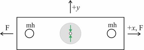
Tensile samples of 1.7 x 5.5 x 0.07 mm3 for the in-situ TEM straining were prepared by spark cutting and grinding. A mounting hole of 0.6 mm in diameter was drilled at each end of the sample (see the figure below). The central part of the specimen was thinned to electron transparency by the double jet electropolishing. The preferred areas of observation are indicated by green arrows.
The samples were strained in tension at room temperature in a JEM 1200EX microscope equipped with a double tilt straining stage (x-tilt 30º, y-tilt 10º, max. load of 25 N) designed and constructed at the Institute of Physics ASCR.
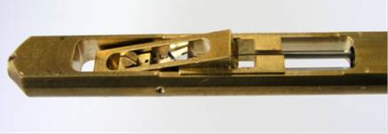
Tip of the specimen holder with the tilting cradle
Twinning processes taking place during loading/unloading were video-recorded by an Olympus Mega View III camera. Only the applied load was recorded during the in-situ TEM experiment, the elongation of the thin foil sample was not evaluated.
For more details of the in-situ TEM straining experimen, including the stress distribution around the hole, see the PPT presentation.
The videos shown below were recorded during the straining in the JEM 1200EX microscope. Detailed structural investigations were carried out under static stress in both the bright field (BF) and dark field (DF). Deformed foils were finally cut to a 3-mm length to fit into a standard double tilt TEM holder, and analyzed using a high-resolution Tecnai F20 200kV FEG microscope.
Twin variant reorientation during straining the NM martensite in NiMnGa
When applying the external load, detwinning process starts by movement of twinning dislocations along the internal twin planes. The twin variants oriented more favorably to the applied stress grow at the expense of the less favorable ones. The process is, however, very fast at the beginning so that motion of individual twinning dislocations can be hardly distinguished.
Movement of twinning dislocations during the twin variant reorientation
As the loading process slows down, movement of twinning dislocations can be monitored as the propagating bow-like contrast. The twin plates are inclined by about 45 degrees to the foil plane and the twinning systems are oriented as shown in the schematic figure.

Movement of twinning dislocations during the twin variant reorientation
Movement of twinning dislocations in another geometrical configuration

Reorientation proces in detail

The microstructure of NM martensite shown in the above videos consists of partly detwinned region M2+M3, where the reorientation M3 → M2 is in progress. The twinning dislocations nucleate at a domain boundary and proceed towards the opposite boundary, where they pile up and, eventually, are incorporated in the boundary.
The white arrow indicates the external loading direction. The white lines mark intersections of the M3 plates with the upper (full) and lower (dashed) surfaces of the foil.
Detail of the twin nucleation is shown in the right figure. The twin dislocations are generated at the intersections of the M3 plates with the domain boundary (inclined by about 45 degrees to the image plane). As soon as the twinning dislocation leave the boundary, the dislocation line changes its direction to take up the shortest length between the top and bottom foil surfaces.
Twinning dislocations in detail
Schrinking plates of M3 martensite variant within M2+M3 region
|
|
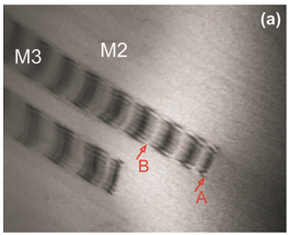
Bright-field image taken in reflection g = 022M2 The contrast has a six-fold periodicity, though it is not well distinguishable because the dislocations are very densely distributed at the ends of the disappearing M3 plates.There are three strips without contrast in section A−B, which means that there should be 18 dislocations (expanation of the TEM contrast – see below, in Section „Mechanism of twinning via motion of twin dislocations“). |
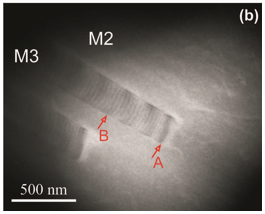 |
Dark-field image taken in reflection g = 0012M2. Individual dislocations are visible as fine dark lines in this reflection. There are 18 dislocations between marks A and B; their separation is about 30 nm. |
Twinning of NM martensite upon unloading
So far the presented videos demonstrated only the detwinning processes taking place upon tensile loading. However, when the sample is unloaded, we clearly see the reverse process (i.e. twinning). The bow contrast, i.e. the twinning dislocations, move in the opposite direction than they moved when under increasing stress. This contradicts the experimentally observed irreversibility of macroscopic twinning strains. The key is probably the hysteresis width and the local stress state which is unknown here.
Mechanism of twinning via motion of twinning dislocations
Reorientation of the martensite variants takes place by propagation of the twin interfaces. It proceeds via motion of twinning dislocations which glide on the successive twin planes and transform thus one martensite variant into the other.
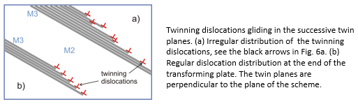
In the following explanation we go back to the micrographs shown in Section „Reorientation process in detail". Six levels of the contrast observed in reflection g = 022 are numbered 1 to 6 in the figure, and the black arrows highlight the positions of the twinning dislocations. The dislocations are distributed rather irregularly. Regular dislocation distribution is observed at the ends of the disappearing M3 plates, as indicated by the periodically changing contrast. The pronounced changes in contrast observed on the transforming plates are due to a set of twinning dislocations gliding in the neighboring twin planes, as shown in the scheme below.
Analysis of the reorientation mechanism is based on the analysis of the TEM contrast.
The twin planes of the compound twins are (022)-type planes in martensite. For the variant combination M2 + M3, the twin planes are (202)M2 or (20-2)M2 planes.
The direction of the Burgers vector of the twinning dislocations is b = [-101]M2 or [101]M2, determined from the g.b = 0 invisibility criterion, where g is the reflection in which the image was taken.
The size of the Burgers vector is determined from the periodicity of the contrast on the transforming variant plates. The moving twinning dislocations are followed by α-fringes (appearing as the bright and dark lines parallel to the intersection of the twin plate and the foil surface). The changing contrast on the transforming plate is the result of variations in the lattice displacement and twin plate thickness, both due to the movement of twinning dislocations. The changes in the contrast correspond to the phase differences α = 2π(g.b), 2π(g.2b), etc., produced by an array of twinning dislocations with the Burgers vector close to 1/12[101] gliding in the successive (20-2) planes. For g = 022, a train of twinning dislocations with the Burgers vector 1/12[101] will yield a six-fold contrast, α = π/3, 2π/3, π, 4π/3, 5π/3, 2π, as indicated by the numbered segments of equal contrast in the figure shown in Section „Reorientation process in detail". Segment 6 is without contrast, in agreement with the fact that no contrast occurs for α = 2nπ (n = integer). For g = 0012 (see figure (b) in Section „Twinning dislocations in detail“), α = 2π(g.b) = 2π.1/12[101].[0012] = 2π. The α-contrast disappears and the individual dislocations are visible as fine dark lines.
The process of twin interface propagation via motion of twinning dislocations is schematically visualized in the scheme and animation below. The tetragonal NM martensite is projected along the [0-10] lattice vector. Twin dislocations move on the successive (20-2) planes in the [101] direction. The half-planes limited by the dislocations are close to (9 0 -13) in the tetragonal structure. For details on the twinning mechanism, see recent article Deformation Twinning in Ni2MnGa by Pond et. al.

Literature
[1] Dlabáček Z, Gemperle A, Gemperlová J. Proc. 13th European Microscopy Congress 2004;1:417
[2] Coujou A, Lours Ph, Roy NA, Caillard D, Clement N. Acta Metal 1990;38:825
[3] Zárubová N, Gemperle A, Gemperlová J. Mater Sci Eng A 2007;462:407
[4] Ullakko K, Huang JK, Kanter C, O’Handley RC, Kokorin VV. Appl Phys Lett 1996;69:1966
[5] Söderberg O, Ge Y, Sozinov A, Hannula S-P, Lindroos VK. Smart Mater Struc 2005;14:S223
[6] Söderberg O, Aaltio I, Ge Y, Heczko O, Hannula S-P. Mater Sci Eng A 2008;481:80
[7] Sozinov A, Lanska N, Soroka A, Zou W. Appl Phys Lett 2013;102:021902
[8] Zárubová N, Ge Y, Heczko O, Hannula S-P. Acta Mater 2013;61:5290
[9] Zárubová N, Ge Y, Gemperlová J, Gemperle A, Hannula S-P. Func Mater Lett 2012;5:1250006
[11] Pond RC, Muntifering B, Müllner P. Acta Mater 2012;60:3976
Quick Links
Copyright © 2015 OFM AV ČR, v. v. i.